One of the emerging high-speed switching technologies which will support a wide variety of medical imaging and data applications is ATM (Asynchronous Transfer Mode). It offers the performance advantages of switched connection-oriented channels, and allows users to avoid the bandwidth problems inherent in shared-media networking systems. Key benefits of ATM include:
The goal at OSF Healthcare Systems was to design a network where the patients' clinical and financial data could follow them throughout the system whether at the hospital, a patient-care facility, or the doctor's office. This patient-centered data network would:
In the early phases, OSF plans to use ATM within Peoria over local and metropolitan area networks, while using frame relay to tie-in remote sites. However, as the cost of ATM falls, it is hoped that all the sites within the OSF Healthcare system will be connected via ATM-based networks. To demonstrate the switching technology in a patient-centered data network, it was decided to implement a test ATM-based local teleradiology network. The remainder of this article details the ATM test project and reviews the overall project status to date.
THE SFMC ATM NODE
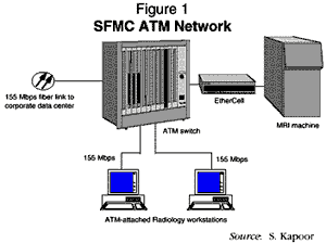
Figure 1 illustrates the ATM node deployed at the SFMC. It consists of an ATM switch, an EtherCell, SUN workstations, and an MRI machine. The principal goal is to demonstrate the ability to transfer radiology images from the MRI machine to a UNIX-based workstation via the ATM switch. Note that the MRI machine is on an Ethernet network attached to the EtherCell which, in turn, is connected to the ATM switch via a fiber-optic connection at 155 Mb/s. The patient study (a collection of patient images) can be shared between two radiologists (workstations) within the same physical facility or between different facilities. Currently, the images (in hard copy film) are sent between facilities via courier which can take anywhere from several hours to several days depending on the location.

ETHERCELL FEATURES
The EtherCell shown in Figure 1 has 12 Ethernet ports and one ATM port. Each of the 12 ports provides a 10 Mb/s dedicated Ethernet segment to which individual servers/PCs or conventional Ethernet HUBs (with several clients attached to these HUBs) can be attached. The ATM port (155 Mb/s) connects to an ATM switch. It is perfectly suited for building hybrid Ethernet/ATM networks. The main features of the EtherCell are highlighted below:
THE ATM SWITCH
The LattisCell™ ATM switch facilitates call set-up between network end points with the flexibility of allocating precise bandwidth, quality of service, and performance guarantees. Each of the switches deployed in the OSF network have 16 individually configured user-defined ports, each operating at 155 Mb/s. The bandwidth requirements of the individual ports can be configured via software at connection set-up. For example, a videoconferencing session between ports three and four could be allocated 32.45 Mb/s if desired. When a connection is requested, the switch determines if there are available resources; if there are not, the request is denied. This type of performance guarantee is not available with conventional shared bandwidth media or switched media. Some of the main features of the switch are that it:
TYPES OF CIRCUITS
The concept of virtual connections is similar to traditional switching networks, but the actual mechanics are different. There are two basic types of virtual circuits: switched and permanent.
A switched virtual circuit is dynamically established on an as-needed basis. A Virtual Circuit Identifier (VCI) and Virtual Path Identifier (VPI) are established for each direction of communication. Therefore, for every full-duplex SVC connection, there will be two pairs of VPI/VCI assigned by the switch. To benefit fully from ATM switching technology, SVC implementation is a must because this allows users to add and delete connections dynamically.
A permanent virtual circuit is established from a source end-point to a destination end-point without the ability to dynamically release the connection. PVCs are manually established and must be manually released.1
THE RADIOLOGY WORKSTATION
The radiology workstation is UNIX-based, with an ATM network interface card that enables it to connect to the ATM switch at 155 Mb/s. Figure 2 shows the ATM protocol architecture. SONET and ATM form layers one and two respectively. The ATM Adaptation Layer (AAL5) forms the periphery of the ATM network, which converts conventional LAN packets into ATM cells and vice versa. Upper layer protocols, such as Internet Protocol (IP) and Internet Packet Exchange Protocol (IPX), are encapsulated within LAN emulation headers before being segmented into ATM cells.
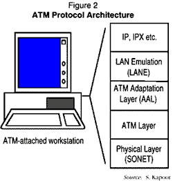
The ATM interface cards have several software components, including:
LAN Emulation2 (LANE) allows ATM attached workstations to communicate with Ethernet attached workstations. The LANE software running on the ATM clients emulates the client as if it were on an Ethernet network. The advantages of LANE are that it:
The ATM forum specifies that the key to handling multicast/broadcast traffic from an Ethernet LAN is a Broadcast Unknown Server (BUS). To function as today's shared LANs, the LAN Emulation Configuration Server (LECS) enables switched LANs to be configured in broadcast domains or virtual LANs. Each emulated LAN receives and broadcasts traffic over its own specific BUS call tree. The LAN Emulation Server (LES) uses its own call tree to perform various tasks such as address resolution. LANE deliberately hides the ATM, allowing virtually any network layer to operate over ATM.
User-Network Interface (UNI) signaling, as defined by the ATM Forum, specifies how a client will communicate with an ATM switch.
SVC operation allows ATM-attached clients to dynamically set up connections as and when required.
The Interim Link Management Interface (ILMI) protocol uses Simple Network Management Protocol formatted packets across either a User-Network Interface or Network-to-Network Interface to access the ILMI Management Information Base for that particular link. The most important feature is address registration that facilitates the registration of ATM addresses.
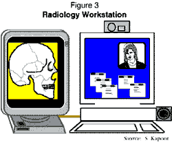
Figure 3 illustrates a typical radiology workstation with ATM connectivity. We have attached an external high-resolution monitor for viewing x-rays. The features of this workstation include:
Using videoconferencing software, we enable doctors to set up a full-motion videoconferencing session with CD-quality audio. It is important to stress the audio quality, because this high-quality sound allows doctors to transmit and receive audio clips of a patient's heartbeat, lungs, etc.
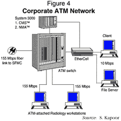
CONNECTION MANAGEMENT SYSTEM FEATURES
The CMS which is responsible for setting up and managing connections within a switch or multiple switches is the heart of the ATM network. Important features of CMS are:
MULTICAST COMMUNICATION SERVER FEATURES
The MCS and the CMS work together to manage the ATM network. There are several important features of the MCS:
NETWORK MANAGEMENT APPLICATION FEATURES
The NMA uses three protocols to communicate with all management agents.
The NMA works with the CMS software to provide a graphical user interface that displays the ATM network and its status in real time.
LattisCell Domain View™ displays the complete network topology by providing a color-coded view, displaying the status of the switches and the associated links. From this domain view, the user can profile a network or clients within that network. For example, you can obtain information on a switch, reset the width, or view bandwidth usage on any particular link.
LattisCell Expanded View™ displays a picture of the front panel of the LattisCell and EtherCell switch. Included in this display are ports and their associated LEDs that turn on and off in real time based on the status of the network. This application also provides pull-down menus that allow the user to enable/disable ports on the switches.
NetWare™ Connectivity is included to demonstrate transparent communication between a Novell file server and its associated clients through the EtherCell. The EtherCell supports up to 1,024 Ethernet clients on the ATM backbone. The primary benefits of using the EtherCell are that it:
Ethernet-ATM Connectivity via IP demonstrates transparent communication between Ethernet and ATM clients, i.e., between PCs (loaded with TCP/IP stacks) and ATM-attached SUN workstations running the LANE specification. The primary benefit of LANE is that the user does not have to manually set up the connections within the ATM switch every time an Ethernet client wants to communicate with an ATM client.
Native ATM Connectivity demonstrates some of the applications that will run over an ATM-based network linking ATM-attached workstations at different physical sites. Demonstrated applications will include:
Videoconferencing will demonstrate conferencing capabilities between SUN workstations at a full 30 frames per second using commercially available frame grabbers and small cameras mounted on the workstation itself. This will allow doctors to visually communicate with colleagues and share data (text and images) simultaneously. To connect to another user, one has only to select the user name from a given list. The connection through the switch/network is automatically set up.
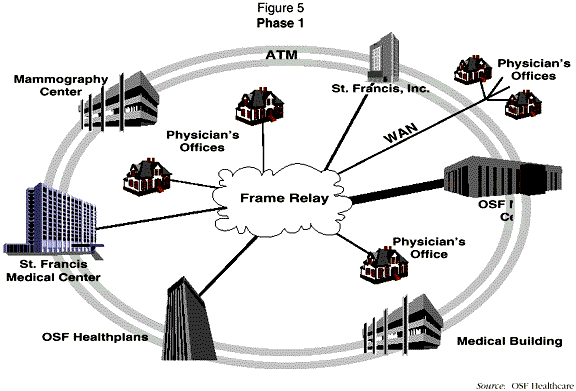
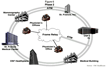
In Phase 2, we plan to have direct connectivity between frame relay and ATM via the service provider's switch (Figure 6). We are currently working with several service providers, including independents and competitive access providers. The prices being quoted on 155 Mb/s SONET services are attractive enough to warrant deployment projections of ATM across the metropolitan area and beyond.
The focus of this article was to demonstrate the feasibility of ATM as a viable backbone technology for medical applications such as teleradiology. I strongly believe that ATM is a cost-effective and technically viable technology that will enable us to share valuable resources such as medical expertise, images, and data among facilities and negate geographic distances.